Numerical Inverse Kinematics#
Recall the problem of Inverse Kinematics (IK): given \(\boldsymbol{x}_{d}\) (the desired end-effector pose in the operational space), we want to find the joint value \(\boldsymbol{q}\) such that \(\boldsymbol{k}(\boldsymbol{q})=\boldsymbol{x}_d\). Here, \(\boldsymbol{k}(\cdot)\) is the forward kinematics.
To solve the above IK, we define the following operational space error between the desired \(\boldsymbol{x}_{d}\) and the current end-effector pose \(\boldsymbol{x}_{e}\):
Consider the time derivative
The above is called error dynamics (an Ordinary Differential Equation), as it shows the profile of the operational space error \(\boldsymbol{e}(t)\) over time \(t\). Here, \(\dot{\boldsymbol{q}}\) can be viewed as the control input. From a control perspective, we want to find a feedback control law
such that, when plug the controller to the error dynamics, \(\boldsymbol{e}(t)\rightarrow 0\) as \(t\rightarrow \infty\). The different controllers leads to different numerical IK algorithms.
Controller 1: Jacobian (Pseudo-)Inverse or Newton-Raphson Method#
Let’s define \(\dot{\boldsymbol{q}}= \text{Controller}({\boldsymbol{x}}_d, \dot{\boldsymbol{x}}_d, {\boldsymbol{q}}, {\boldsymbol{e}})\) specifically as
Submitting the above controllers into the error dynamics, it easy to verify that
If \(\boldsymbol{K}\) is a positive definite (usually diagonal) matrix, the above is asymptotically stable. The error tends to zero along the trajectory with a convergence rate that depends on the eigenvalues of \(\boldsymbol{K}\).
Background from Linear Control Systems course
Generally, given an ordinary differential equation (ODE) $\(\dot{\boldsymbol{e}}+\boldsymbol{K} \boldsymbol{e}=0 .\)\( the solution \)\boldsymbol{e}(t)$ to the ODE is
In particular, if \(\boldsymbol{K}\) is diagonal, say
Then, the solution is
Therefore, only if \(\lambda_1, \lambda_2, ...\lambda_r>0\), \(\boldsymbol{e}(t)\rightarrow \boldsymbol{0}\) as \(t\rightarrow \infty\).
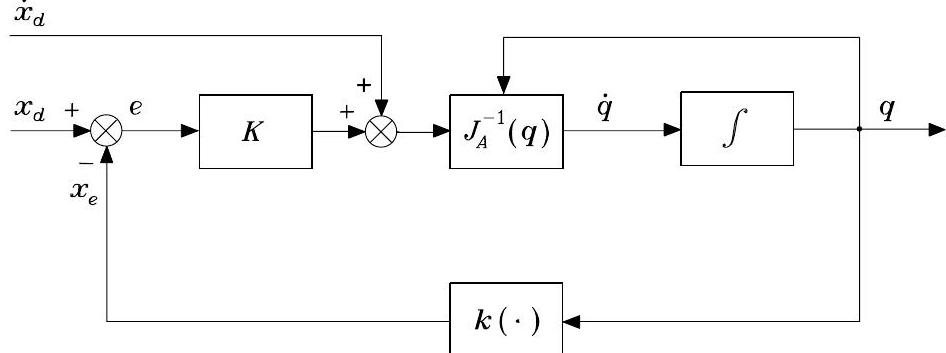
The block scheme corresponding to the IK algorithm is illustrated below, where \(\boldsymbol{k}(\cdot)\) indicates the direct kinematics function.

Fig. 61 IK algorithm with Jacobian inverse#
Another perspective to look at the above Jacobian Inverse Controller
Another perspective to look at the above Jacobian Inverse Controller is through Newton-Raphson method in solving nonlinear equations**
Specifically, consider the following nonlinear equation from kinematics
given the desired end-effector pose \(\boldsymbol{x}_d\).
Assume we are given the current initial guess \(\boldsymbol{q}_t\). One can approximate the above kinematics at \(\boldsymbol{q}_k\) using the first-order Tyler expression:
By solving the above equation for \(\boldsymbol{q}\), one can obtain the next updated guess
where \(\text{inv}\) is the general inverse operation (inverse for square matrix or pseudo-inverse for non-square matrix). Typically, one also needs a step size before \(\text{inv}\left(\boldsymbol{J}(\boldsymbol{q}_t)\right)\) to stabilize the Newton-Raphson algorithm. The above results can be considered as the discrete-time interpretation of the Jacobian Inverse IK algorithm if \(\dot{\boldsymbol{x}}_d=\boldsymbol{0}\).
Controller 2: Jacobian Transpose or Gradient-Based Method#
Background about Lyapunov Stability
Consider the following error dynamics (ODE) $\(\dot{\boldsymbol{e}}(t)=\boldsymbol{f}(\boldsymbol{e}(t)),\quad \text{given}\quad \boldsymbol{x}(0)\)$
If there exists a Lyapunov function \(V(\boldsymbol{e})\) such that
\(V(\boldsymbol{e})>0 \quad \forall \boldsymbol{e} \neq \mathbf{0}\)
\(V(\mathbf{0})=0 \quad \text{only for} \quad \boldsymbol{e}=\boldsymbol{0}\)
\(\dot{V}=\frac{dV}{dt}=(\frac{d V}{d\boldsymbol{e}})^T\dot{\boldsymbol{e}}=(\frac{d V}{d\boldsymbol{e}})^T \boldsymbol{f}(\boldsymbol{e}(t))<0 \quad \forall \boldsymbol{e}\)
then, \({\boldsymbol{e}}(t)\rightarrow \boldsymbol{0}\) as \(t\rightarrow \infty\) (the error is converging).
Consider \(\dot{\boldsymbol{x}}_{d}=\mathbf{0}\). Let’s use Lyapunov function to find another controller such that the error dynamics is converging. Let’s choose Lyapunov function as
where \(\boldsymbol{K}\) is a symmetric positive definite matrix. Obviously,
Differentiating \(V(\boldsymbol{e})\) with respect to time gives
At this point, since \(\boldsymbol{\dot{x}}_d=\boldsymbol{0}\), if we choose
This leads to
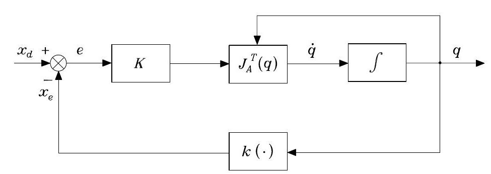
\(\dot{V}\) is negative definite, under the assumption of full rank for \(\boldsymbol{J}_{A}(\boldsymbol{q})\). \(\dot{V}<0\) with \(V>0\) implies the error dynamics will converge/stabilize to \(\boldsymbol{e}=\mathbf{0}\), according to Lyapunov Stablity. The block scheme is illustrated below.

Fig. 62 Block scheme of the inverse kinematics algorithm with Jacobian transpose#
Another perspective to look at Jacobian transpose controller
Specifically, when \(\dot{\boldsymbol{x}}_d=\boldsymbol{0}\), consider we want to find the joint value \(\boldsymbol{q}\) by minimizing the error of
The gradient descent to update current guess \(\boldsymbol{q}_k\) to next \(\boldsymbol{q}_{k+1}\)
where \(\alpha\) is the gradient step size. The above results can be considered as the discrete-time interpretation of the Jacobian transpose IK algorithm if \(\boldsymbol{\dot{x}}_d=0\).
More Discussion#
When \(\dot{\boldsymbol{x}}_{d} = \mathbf{0}\) and \(\mathcal{N}\left(\boldsymbol{J}_{A}^{T}\right) \neq \emptyset\), \(\dot{V}\) is only negative semi-definite, since \(\dot{V}=0\) for \(\boldsymbol{e} \neq \mathbf{0}\) with \(\boldsymbol{K} \boldsymbol{e} \in \mathcal{N}\left(\boldsymbol{J}_{A}^{T}\right)\). In this case, the algorithm can get stuck at \(\dot{\boldsymbol{q}}=\mathbf{0}\) with \(\boldsymbol{e} \neq \mathbf{0}\).
When \(\dot{\boldsymbol{x}}_{d} \neq \mathbf{0}\), in order to obtain \(\dot{V}<0\) also in this case, it would be sufficient to choose
which is exactly the Jacobian inverse controller introduced in the first section.
Furthermore, we have the following comments on the above Jacobian transpose controller.
In the case of kinematic singularities, we have to use Jacobian transpose IK because it does not require the inverse/pseudo-inverse of the Jacobian
Although the Jacobian transpose IK cannot guarantee the convergence of the error dynamics when \(\dot{\boldsymbol{x}}_{d} \neq \mathbf{0}\), the tracking error \(\boldsymbol{e}(t)\) is norm-bounded. This is because, when the error norm is small, the linear term (the first term in \(\dot{V}(t)\)) prevails in the second quadratic term; when otherwise, the quadratic term dominates, dragging the error to the small norm.
Definition of Orientation Error#
Both IK algorithms above require the definition of the error in the operational space (note that we have used the analytical Jacobian instead of the geometric Jacobian). This is natural for the position part of the end-effector
where \(\boldsymbol{p}_{d}\) and \(\boldsymbol{p}_{e}\) denote respectively the desired and computed end-effector positions. Its time derivative is
However, the problem arises when we consider defining the orientation error, which depends on the representation of the orientation. In the following, let’s consider the typical types of orientation representation and its error.
Euler-Angles Error#
The orientation error using Euler angles is
where \(\boldsymbol{\phi}_{d}\) and \(\boldsymbol{\phi}_{e}\) denote respectively the desired and computed set of Euler angles. Its time derivative is
The analytical Jacobian for ZYZ-Euler angles was given in previous lectures: \(\boldsymbol{J}_{A}=\boldsymbol{T}^{-1}\boldsymbol{J}\) with \(\boldsymbol{J}\) being the geometric jacobian and
Angle-Axis Error#
If the desired orientation of the end-effector is given in rotation matrix \(\boldsymbol{R}_{d}=\left[\begin{array}{lll}\boldsymbol{n}_{d} & \boldsymbol{s}_{d} & \boldsymbol{a}_{d}\end{array}\right]\) and current end-effector’s rotation matrix is \(\boldsymbol{R}_{e}(\boldsymbol{q})=\left[\begin{array}{lll}\boldsymbol{n}_{e}(\boldsymbol{q}) & \boldsymbol{s}_{e}(\boldsymbol{q}) & \boldsymbol{a}_{e}(\boldsymbol{q})\end{array}\right]\), the orientation error vector can be defined as
where \(\vartheta\) and \(\boldsymbol{r}\) are the angle and axis of the rotation needed to align \(\boldsymbol{R}\) with \(\boldsymbol{R}_{d}\)
Via derivation, one can also obtain
Differentiating the above error vector with respect to time
with
where \(\boldsymbol{S}(\cdot)\) is the skew-symmetric operator. The operational space error
To ensure the error dynamics above is converging to \(\boldsymbol{e}=\boldsymbol{0}\), the Jacobian-inverse controller will be
with
Quaternion Error#
If the desired orientation is given in quaternion \(\mathcal{Q}_{d}=\left\{\eta_{d}, \boldsymbol{\epsilon}_{d}\right\}\) and current quaternion of end-effector is \(\mathcal{Q}_{e}=\left\{\eta_{e}, \boldsymbol{\epsilon}_{e}\right\}\), one can define an error quaternion \(\Delta \mathcal{Q}=\{\Delta \eta, \Delta \epsilon\}\)
which represents the rotation needed to align \(\mathcal{Q}_{e}\) and \(\mathcal{Q}_{d}\). \(\Delta \mathcal{Q}=\{1, \mathbf{0}\}\) if and only if \(\mathcal{Q}_{e}\) and \(\mathcal{Q}_{d}\) are aligned. From the above error quaternion, one can define the orientation error vector
where \(\boldsymbol{S}(\cdot)\) is the skew-symmetric operator. At this point, we define
and set the Jacobian-inverse controller
Next, we will show using the above controller, we will achieve the convergence of \(\mathcal{Q}_{e}\) to \(\mathcal{Q}_{d}\). To do so, we define the following Lyapunov function
It can be shown that
To prove the above, we will need to use the following relationships
which is a result of \(\dot{\boldsymbol{\omega}}_{O}=\boldsymbol{J}_{O}\dot{\boldsymbol{q}}\), and the quaternion derivatives
Second-Order IK Algorithms#
The above IK algorithms can be defined as first-order algorithms, meaning that they convert a motion trajectory, specified at the end-effector in terms of its poses and velocities, into the equivalent joint positions and velocities. Nevertheless, for control purposes, it may be necessary to convert a motion trajectory specified in terms of position, velocity and acceleration into the joint position, velocity and acceleration.
The time differentiation of the differential kinematics leads to
which gives the relationship between the joint accelerations and the operational space accelerations. Following the previous route of defining position and velocity error, we may define the following acceleration error:
Assuming square and non-singular matrix \(\boldsymbol{J}_{A}\), we may choose the controller
where \(\boldsymbol{K}_{D}\) and \(\boldsymbol{K}_{P}\) are positive definite matrices. This controller leads to the equivalent linear error system
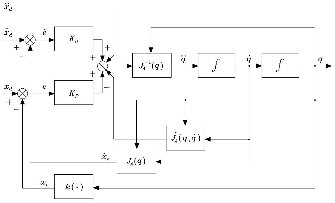
which is asymptotically stable: the error tends to zero along the trajectory with a convergence speed depending on the choice of \(\boldsymbol{K}_{P}\) and \(\boldsymbol{K}_{D}\). The second-order inverse kinematics algorithm is illustrated below.

Fig. 63 Block scheme of the second-order inverse kinematics algorithm with Jacobian inverse#
In the case of a redundant manipulator, the controller is
where the vector \(\ddot{\boldsymbol{q}}_{0}\) represents arbitrary joint accelerations chosen to optimize another objective function.
