Inverse Kinematics#
The inverse kinematics (IK) problem is to determine the joint variables given end-effector position and orientation. The solution to IK is of fundamental importance in order to transform the motion assignment in the end-effector in the operational space into the joint space motions for control purpose. The IK problem is complex since:
Forward kinematics in general are nonlinear, and thus IK is not always possible to find a closed-form solution.
Multiple or infinite solutions may exist for a IK problem, e.g., in the case of a redundant manipulator.
There might be no admissible solutions, in view of the manipulator kinematic limits.
In this lecture, we only talk about the IK problem that permits a closed-form solution. This is only valid for some special-structured kinematic structures. Those IK solutions are all derived based on geometric intuition. For more generalized case of IK, we will leave it after we have learned differential kinematics.
IK of Three-link Planar Arm#
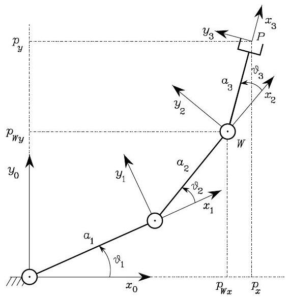
Fig. 41 A three link robot arm#
Suppose the pose of the end-effector is specified with its planar position \((p_{x}, p_{y})\) and the angle \(\phi\) with the axis \(x_{0}\). We want to use IK to find the corresponding joint variables \(\boldsymbol{q}=[\vartheta_{1}, \vartheta_{2}, \vartheta_{3}]\).
To achieve so, we first identify the following relation holds
Also, the following equations can be obtained:
which describe the position of point \(W\), i.e., the origin of Frame 2; depending only on \(\vartheta_{1}\) and \(\vartheta_{2}\).
The cosine theorem to the triangle formed by links \(a_{1}, a_{2}\) and the segment connecting \(W\) and \(O\) gives
Solving \(c_2\) leads to
For the existence of the triangle, it must be \(\sqrt{p_{W x}^{2}+p_{W y}^{2}} \leq a_{1}+a_{2}\). This condition is not satisfied when the given point is outside the arm reachable workspace. Then, under the assumption of admissible solutions, it is
Thus, two admissible \(\vartheta_{2}\) are obtained: the elbow-up posture is obtained for \(\vartheta_{2} \in(-\pi, 0)\) while the elbow-down posture is obtained for \(\vartheta_{2} \in(0, \pi)\), as shown in the figure blow.
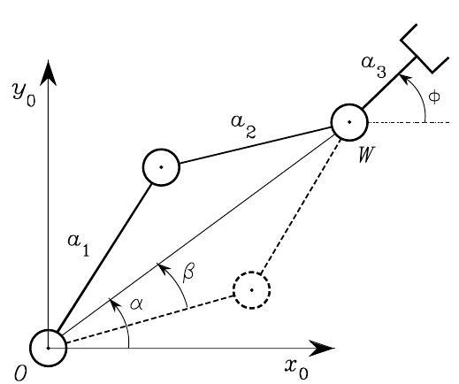
Fig. 42 Admissible postures for a two-link planar arm#
To find \(\vartheta_{1}\) consider the angles \(\alpha\) and \(\beta\) in the above figure. Notice that the determination of \(\alpha\) depends on the sign of \(p_{W x}\) and \(p_{W y}\); then, it is necessary to compute \(\alpha\) as
To compute \(\beta\), applying again the cosine theorem yields
and resorting to the expression of \(c_{2}\) given above leads to
with \(\beta \in(0, \pi)\) so as to preserve the existence of triangles. Then, it is
where the positive sign holds for \(\vartheta_{2}<0\) and the negative sign for \(\vartheta_{2}>0\). Finally, \(\vartheta_{3}\) is computed from ([c1.l2.3link.sum]{reference-type=”ref” reference=”c1.l2.3link.sum”}).
IK of Manipulators of Spherical Wrist#
Most of manipulators are kinematically simple, since they are typically formed by an arm and a spherical wrist. This choice is partly motivated by the difficulty to find IK in the general case. In particular, a six-DOF kinematic structure has closed-form IK solutions if:
three consecutive revolute joint axes intersect at a common point, like for the spherical wrist;
three consecutive revolute joint axes are parallel, like the three-link robot arm
Inspired by IK to a three-link planar arm, an itermediate point on the manipulator can be found, such that the IK problem can be decoupled into two lower-dimentional sub-problems. Specifically, for a manipulator with spherical wrist, the natural choice is to locate such point \(W\) at the wrist position, i.e., at the intersection of the three revolute axes of the wrist. If the end-effector pose is \(\boldsymbol{p}_{e}\) and \(\boldsymbol{R}_{e}=\left[\begin{array}{lll}\boldsymbol{n}_{e} & \boldsymbol{s}_{e} & \boldsymbol{a}_{e}\end{array}\right]\), the wrist position will be
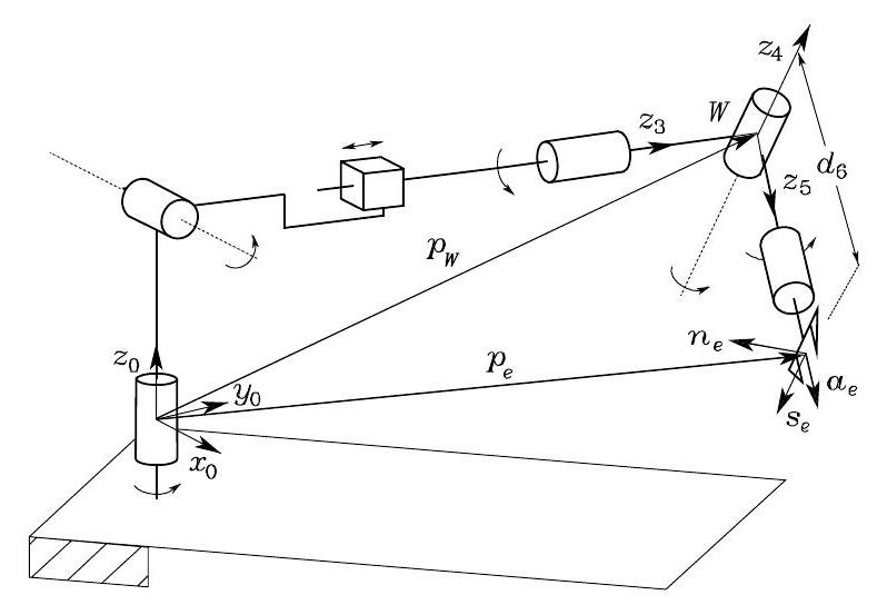
Fig. 43 Manipulator with spherical wrist#
which is a function of the sole joint variables that determine the arm position. Hence, in the case of a (nonredundant) three-DOF arm, the inverse kinematics can be solved according to the following steps:
Compute the wrist position \(\boldsymbol{p}_{W}\left(q_{1}, q_{2}, q_{3}\right)\).
Solve inverse kinematics for \(\left(q_{1}, q_{2}, q_{3}\right)\).
Compute \(\boldsymbol{R}_{3}^{0}\left(q_{1}, q_{2}, q_{3}\right)\).
Compute \(\boldsymbol{R}_{6}^{3}\left(\vartheta_{4}, \vartheta_{5}, \vartheta_{6}\right)=\boldsymbol{R}_{3}^{0 T} \boldsymbol{R}\)
Solve inverse kinematics for orientation \(\left(\vartheta_{4}, \vartheta_{5}, \vartheta_{6}\right)\)
Therefore, on the basis of this kinematic decoupling, IK for the arm separately from the IK for the spherical wrist. Below are presented the solutions for two typical arms (spherical and anthropomorphic) as well as the solution for the spherical wrist.
IK of Spherical Arm#
Consider the spherical arm:
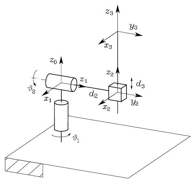
Fig. 44 Spherical arm#
Its kinematics is $\(\boldsymbol{T}_{3}^{0}(\boldsymbol{q})=\boldsymbol{A}_{1}^{0} \boldsymbol{A}_{2}^{1} \boldsymbol{A}_{3}^{2}=\left[\begin{array}{cccc} c_{1} c_{2} & -s_{1} & c_{1} s_{2} & c_{1} s_{2} d_{3}-s_{1} d_{2} \\ s_{1} c_{2} & c_{1} & s_{1} s_{2} & s_{1} s_{2} d_{3}+c_{1} d_{2} \\ -s_{2} & 0 & c_{2} & c_{2} d_{3} \\ 0 & 0 & 0 & 1 \end{array}\right]\)$
To find the joint variables \(\vartheta_{1}, \vartheta_{2}, d_{3}\) corresponding to \(\boldsymbol{p}_{W}=[p_{Wx}, p_{Wy}, p_{Wz}]^T\), we equate the first three elements of the fourth columns of the matrices and thus obtain the following after some equation manipulation
Then, solving the above equation for \(\vartheta_{1}, \vartheta_{2}, d_{3}\) yields
IK of Anthropomorphic Arm#
Consider the anthropomorphic arm:
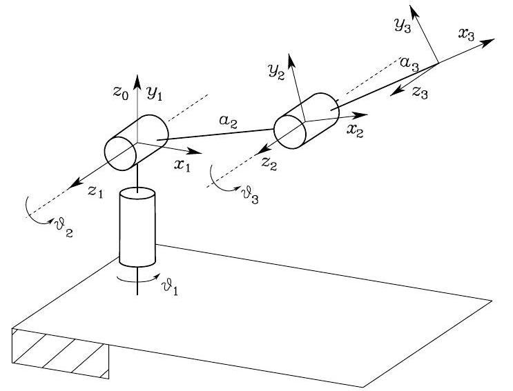
Fig. 45 Anthropomorphic arm#
To find the joint variables \(\vartheta_{1}, \vartheta_{2}, d_{3}\) corresponding to \(\boldsymbol{p}_{W}=[p_{Wx}, p_{Wy}, p_{Wz}]^T\), we equate the first three elements of the fourth columns of the matrices and thus obtain the following
There exist four solutions:
with
which are illustrated below: shoulder-right/elbow-up, shoulder-left/elbowup, shoulder-right/elbow-down, shoulder-left/elbow-down; obviously, the forearm orientation is different for the two pairs of solutions.
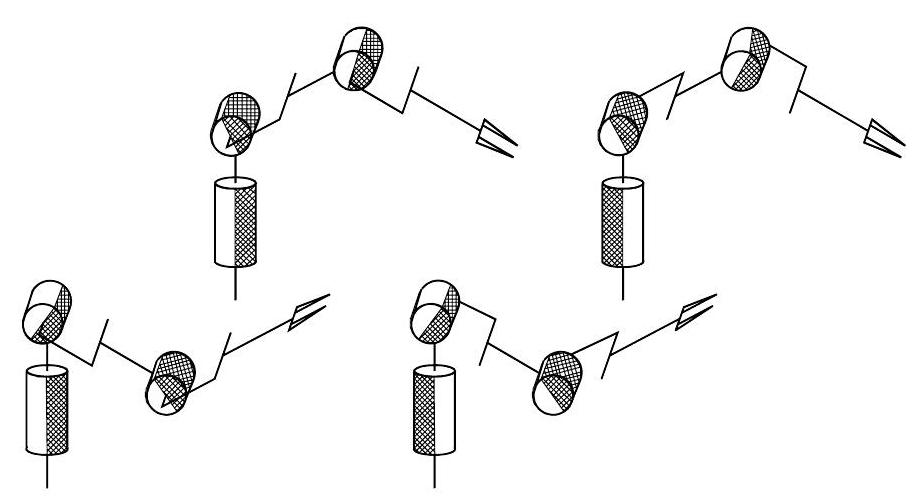
Fig. 46 The four configurations of an anthropomorphic arm compatible with a given wrist position#
IK of Spherical Wrist#
Consider the spherical wrist below.
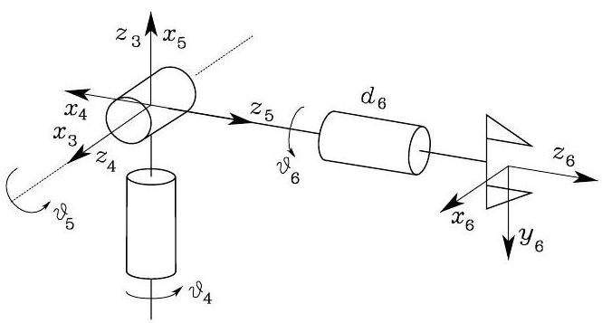
Fig. 47 Spherical wrist#
To find the joint variables \(\vartheta_{4}, \vartheta_{5}, \vartheta_{6}\) corresponding to a given end-effector orientation \(\boldsymbol{R}_{6}^{3}\). As previously pointed out, these angles constitute a set of Euler angles ZYZ with respect to Frame 3.
from its expression in terms of the joint variables, it is possible to compute
for \(\vartheta_{5} \in(0, \pi)\), and
for \(\vartheta_{5} \in(-\pi, 0)\)
